Learning Objectives
- Understand different ways hardware can be controlled via I/O systems.
- Differentiate port-I/O and memory-mapped-I/O.
- Understand how a protocol works in terms of I/O.
- Differentiate between character-oriented and block-oriented I/O.
- Understand the difference between serial and parallel I/O.
Input and Output (I/O)
The term input and output refers to reading (input) and writing (output) to hardware devices. This can be accessories, such as a mouse and keyboard, or peripherals, such as a graphics card or hard drive. Just like everything else with a computer, we need to communicate with these devices by reading and writing to device registers. Recall that a register is just storage for 0s and 1s.
There are two types of registers connected to hardware: (1) status registers and (2) control registers. Status registers are typically set by the hardware device and can be read by a program. This allows us to know what the hardware is doing, in other words, reading the status of the hardware device. On the other hand, a control register can be written to change how the hardware works.
As an example, let's take a GPU. One status register can tell us if a monitor is connected or not. One control registers can be used to change monitor resolutions. This control-and-status is how we can make adjustments and generally make sense of hardware.
Another issues is how to communicate with the hardware. Hardware components are usually connected by some sort of bus and uses a set of rules known as a protocol. Just like a bitmap file makes sense of a sequence of 0s and 1s, a protocol allows us to make sense of a stream of 0s and 1s going to or coming from a hardware device.
PIO and MMIO
Before we even talk about I/O, we have to have some sort of communication channel. There are two types of communication channels we will talk about here: (1) port I/O (PIO) and (2) memory-mapped I/O (MMIO).
PIO and MMIO operate in different address spaces. PIO (port I/O) uses special assembly instructions to communicate with a dedicated IO bus. Recall that a bus is just a bundle of wires that connect multiple devices. Port IO takes care of arbitration (who gets to talk and when). All devices attached to the PIO bus has a small 16-bit address. When we communicate on the bus, all devices hear the same 0s and 1s. However, only the device who has that address will actually take note. Everyone else discards the 0s and 1s.
MMIO is much simpler. MMIO stands for memory-mapped I/O. When we connect devices to the motherboard (the component that connects the CPU with all other external devices, including peripherals and RAM), we can map the device's registers into RAM's address space.
MMIO uses the memory controller to arbitrate between RAM and the devices. This is the preferred method for simpler, embedded systems since a dedicated I/O bus is not necessary. With MMIO, the chip manufacturer will connect the device to a certain memory address. It is incumbent upon the programmer to know what address to look at. Whenever the memory controller sees this address, it knows that it is a device address and NOT a RAM address, so it redirects the 0s and 1s to that device. Recall that we have control and status registers inside of a device. These registers are what are connected to these memory addresses. What makes this simple is that all you have to do is set a pointer and dereference it!
Many systems come with a memory map, as shown below, which describe which memory address have been connected to devices instead of RAM. Here's an example.
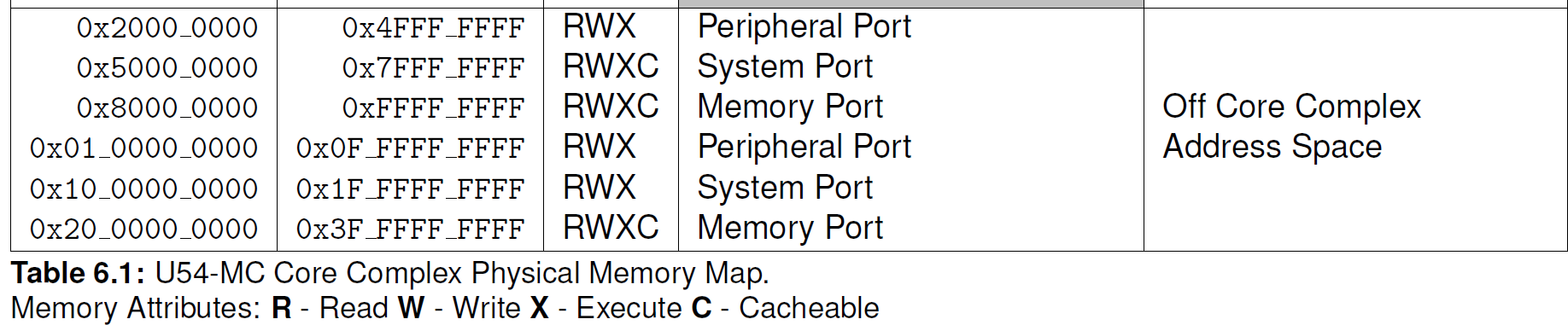
As you can see above, the memory address 0x2000_0000 is NOT RAM. Instead, this will connect us to the peripheral port. It isn't important to distinguish the peripheral or system ports. However, take a look at our RAM, it's actually connected at 0x8000_0000 and 0x20_0000_0000. This might look weird, but it's because the system I'm showing above is a 64-bit system, and NOT a 32-bit system.
Say we wanted to communicate with the peripheral port, with MMIO, we just need a pointer. 0x2000_0000 is called the base address. There are several devices that can be connected here, but let's just assume for the sake of this example that our device's control register is connected at 0x2000_0010, and that the register is 2 bytes (a short). To communicate with this register, we just need to do the following.
int main() {
   volatile unsigned short *dev = (unsigned short *)0x20000010;
   *dev = 1 << 2;  // Set bit index 2
   printf("Device gave us %d\n", *dev);
   return 0;
}
It's not important to know what setting bit index 2 does. I just made that up. We'd actually have to look at the devices technical specification to see what bits in the device's control register does what. Instead, all I'm showing above is that we can use a pointer to communicate with an MMIO-connected device. These specifications usually provide a table that shows a base address followed by offsets. The base is the memory address where the first register is connected. The offsets are numbers added to the base address to get to particular registers. The able below is an example of a base/offset table:
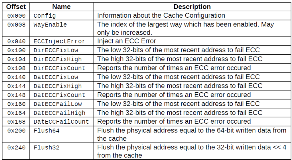
One thing you might be unfamiliar with is the keyword volatile. This keyword disables the C++ compiler's optimizer for this pointer. C++ thinks that we as the programmer are the only one that can set and clear bits. However, remember, status bits are being set by the hardware device. C++ won't know this, and without the volatile keyword, C++ doesn't expect any register to change without US as the programmer changing it. When we add the volatile keyword, we're telling C++ that the value at that memory address can change without us doing anything.
To recap, PIO requires special assembly instructions to communicate on a dedicated IO bus, whereas MMIO uses simple loads and stores to communicate using the memory controller.
Character Oriented I/O
Character oriented I/O refers to a IO system where we read about one-byte (one character) at a time. I say about because sometimes this can be a bit smaller than one byte or somewhat larger than one byte. However, the point of character I/O is that one of our status registers is used as a receiver which contains data the device wants to communicate with us, and one control register is used as a transmitter which we as the programmer put data in to send over to the device.
Think about the console that we use. This is a character-oriented IO device. Whenever we type something on the keyboard, it goes to the console. One of the status registers tells us that there is data ready. Whenever our program sees this, it can then read the receiver register, which will contain which key was pressed. Whenever the console wants to put text to the screen, the program we use (printf, cout, etc) will write the character into the transmitter control register, which then gets printed to the screen.
Block Oriented I/O
A different style of I/O is known as block-oriented IO. Hard drives and other large data IO systems use block-oriented IO. In this case, we still have control and status registers, but the point of these registers is to set up a central communication channel. Generally, we use a place in RAM as our communication channel. We then use the control register to tell the hardware device what memory address it needs to look into. Whenever we want to communicate, we write our request in that memory location and then press the "GO" button by writing to a specific control register (usually called a notify register). This tells the hardware device that we did something, anything. The hardware device then goes to the pre-configured memory address to see what we actually wrote.
The reason we call this block-oriented I/O is because we transfer blocks. For hard drives, the blocks are usually 512 bytes or even 1024 bytes at a time. This is why we need to use RAM to store this. A register that stores 512 or 1024 bytes would be cumbersome, plus we don't have a data type that stores 512 or 1024 bytes at a time. So, instead, we use memory as the central communication channel. We only use the status and control registers to tell the hardware device that something happened and to configure what memory address both we and the hardware device are going to use.
Serial vs Parallel I/O
We used to have PATA (parallel-ATA) that connected our hard drives to a bus. Now, we have SATA (serial-ATA). So, you might think that serial is better than parallel? What's the difference.
Serial refers to the fact that one follows another. That is, when I want to transmit 8 bits, I send one at a time and toggle a clock each time. This means it takes 8 clock cycles to read 8 bits.
Parallel refers to the fact that more than one bit is signaled simultaneously. If we had 8 wires connecting 8 bits, it would only require 1 clock cycle to read 8 bits.
A serial I/O only needs two wires: the clock and the value, whereas our parallel I/O needed at least 9 wires (8 for the data and 1 for the clock). Not all I/O protocols follow this, but it suits our example.
Serial has been preferred over parallel mainly to reduce the number of inputs and outputs a device needs to have. The Universal Serial Bus (USB) only requires 4 pins: (1) power, (2) transmit, (3) receive, (4) ground. The newer and faster versions have more pins, but you can see with just four pins, we can do a lot of work!
Serial performance is highly dependent on clock speed, whereas parallel performance is highly dependent on the cable. You see, the smaller diameter of wire we have, the more resistance and heat we get over a longer distance. This heat steals away our signal and noise can be injected by alternating current and other signals.