Learning Objectives
- Understand what instructions look like in machine code.
- Understand and be able to encode registers by name and by number.
- Understand what an opcode is and what it is used for by the CPU.
- Be able to encode and decode given instructions.
- Understand how branch offsets work and how to encode them.
- Understand which branch instructions have encodings and which do not.
- Understand limitations of branch and jump instructions.
You will need to use the MIPS Instruction Set Manual for this lecture. We will mostly be using Appendix A to decode instructions and Chapter 3 to encode instructions.
Encoding Instructions
The base MIPS32 instruction set architecture (ISA) lays out 32 bits for every instruction. This means each instruction has a fixed size. This is not always the case. For example, the AMD/Intel processors have a variable length encoding. In these cases the first byte relays information on whether a second or third or fourth ... and on and on are necessary.
Instructions are blocks of 32 1s and 0s, thus they are 32 bits. Here is an example of an instruction encoding as shown in the MIPS32 ISA manual.
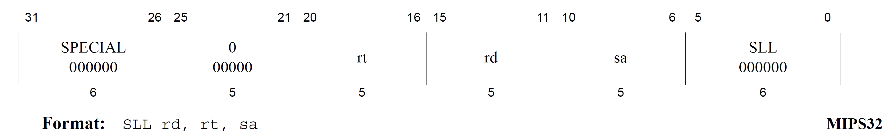
You can see the instruction goes from bits 31 down to 0, which is 32 total bits. The first 6 bits (labeled SPECIAL above) is called the opcode. This allows the CPU to distinguish one instruction from another. There are several instructions under the SPECIAL opcode, so the lower 6 bits (labeled SLL above) becomes the secondary OPCODE. So, the CPU starts by reading the first 6 bits. This will narrow down the instruction considerably. In our case above, this narrowed us down into the SPECIAL category. When the CPU sees this, it reads the lower 6 bits to find out that this is the SLL (shift left, logical) instruction.
You can see a combination of fields where a value is given to you, such as the OPCODE, the next 5 bits, which are all 0, and finally the SLL, which again, is 6 zeroes. Then, there are three fields that have a label. These are: rt, rd, and sd. The values prefixed with an r stand for register whereas sa stands for shift amount.
We know the SLL instruction takes a destination register, a source register, and a shift amount. So, to distinguish which register is which, we look again in the document for the description, which shows the following.
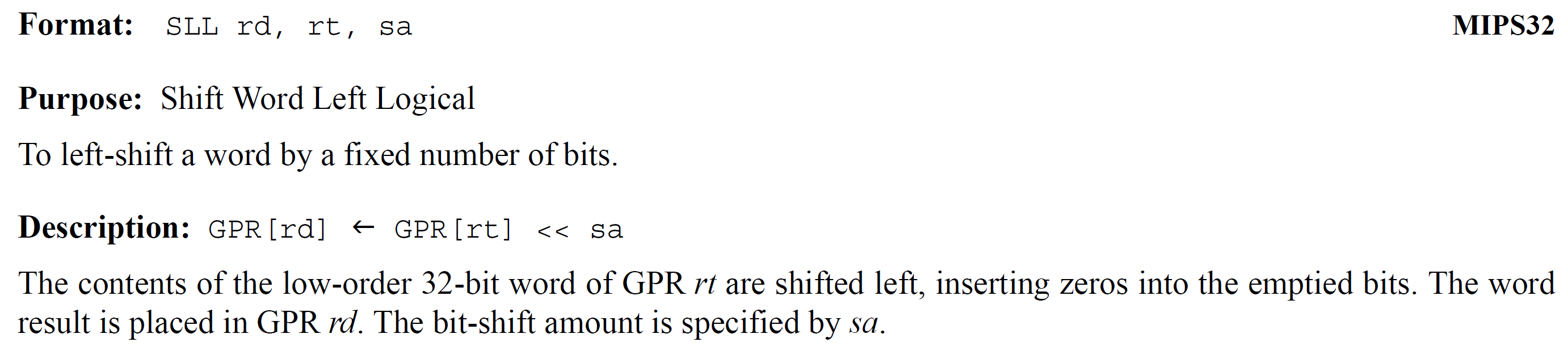
Using the description we see that the contents of GPR (general purpose register) in rt is shifted left by the value of sa. Each of these is encoded using 5 bits, why? Well, \(2^5=32\) and we have exactly 32 registers. The shift amount is the same because we have 32 bits in each register, so we need to be able to shift at least 0 through 31 places.
The registers are all numbered. Recall that we can refer to a register by its number or by its name. The table below shows side-by-side each register's number with its name.
| Number | Name | Description |
|---|---|---|
| 0 | $zero | Always zero |
| 1 | $at | Don't use. Assembler temporary |
| 2 - 3 | $v0 - $v1 | Return registers |
| 4 - 7 | $a0 - $a3 | Argument registers |
| 8 - 15 | $t0 - $t7 | Temporary registers |
| 16 - 23 | $s0 - $s7 | Saved registers |
| 24 - 25 | $t8 - $t9 | Temporary registers (more) |
| 26 - 27 | $k0 - $k1 | Kernel use registers |
| 28 | $gp | Global pointer |
| 29 | $sp | Stack pointer |
| 30 | $fp | Frame pointer |
| 31 | $ra | Return address |
So, let's see how to encode the instruction SLL $t0, $s3, 3.
SLL $t0, $s3, 3
000000  00000   rt   rd   sa  000000
rt = $s3 = 19 = 0b10011
rd = $t0 = 8 = 0b01000
sa = 3 = 0b00011
OPCODE  0      rt     rd     sa     SLL
000000  00000  10011  01000  00011  000000
0000 0000 0001 0011 0100 0000 1100 0000
0    0    1    3    4    0    c    0
So, we can see that we encode the instruction as 0x0013_40c0. So, the CPU will read 0x0013_40c0 and know that it is a shift left, logical which shifts $s3 left three places and stores the result into $t0. Pretty nifty, ain't it?
So, when you're approached with a question, "how does this instruction encode?" take the following steps.
- Open the MIPS ISA manual.
- Look in Chapter 3 for the instruction's name.
- Go to the page to find the instruction diagram.
- Write down all bits already given to you (opcode and/or sub-opcode).
- Determine correct order of registers.
- Convert register names to register numbers.
- Put all bits together.
Pseudo-instructions
The manual only shows actual instructions. Pseudo-instructions encode into other, real instructions. For example, load immediate (li) actually uses addiu. li $a0, 100 is the same as addiu $a0, $zero, 100. However, if you tried to look for li in the manual, you wouldn't find it. Don't get swindled by pseudo-instructions!
Decoding Instructions
Say we're given the hex or binary machine code, and we want to find what instruction it actually is. We can do this by referring to Appendix A in the MIPS ISA manual. As I showed in the encoding section, we look at the upper 6 bits, which is the opcode. This will narrow down our search. Let's take our original example to see if we can get SLL $t0, $s3, 3 back out of it.
0x0013_40c0 = 0000_0000_0001_0011_0100_0000_1100_0000
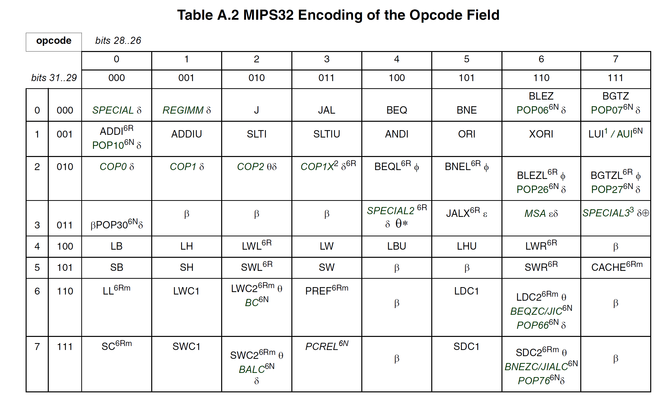
Our opcode = 000_000, so we turn to table A.2, which is the opcode table, shown below.
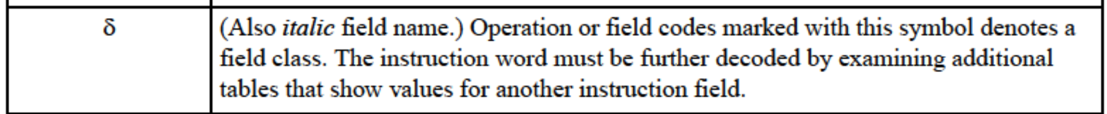
There are several special symbols, which are explained in the preceding pages of the ISA manual. I won't explain them here.
The 6-bit opcode is split into two 3-bit opcodes. The row is the first three bits and the column is the second three. Our opcode is 000_000, so the first three bits 000 show us row 0 and the second bits 000 show us column 0. When they meet, we see that our opcode matches SPECIAL. The symbol means that this is a field class and not a single instruction. This just means we have another field to distinguish what instruction we're talking about. This additional field is called the sub-opcode.
So, we know that this is a SPECIAL opcode, so we need to turn to the SPECIAL opcode table (A.3) shown below.
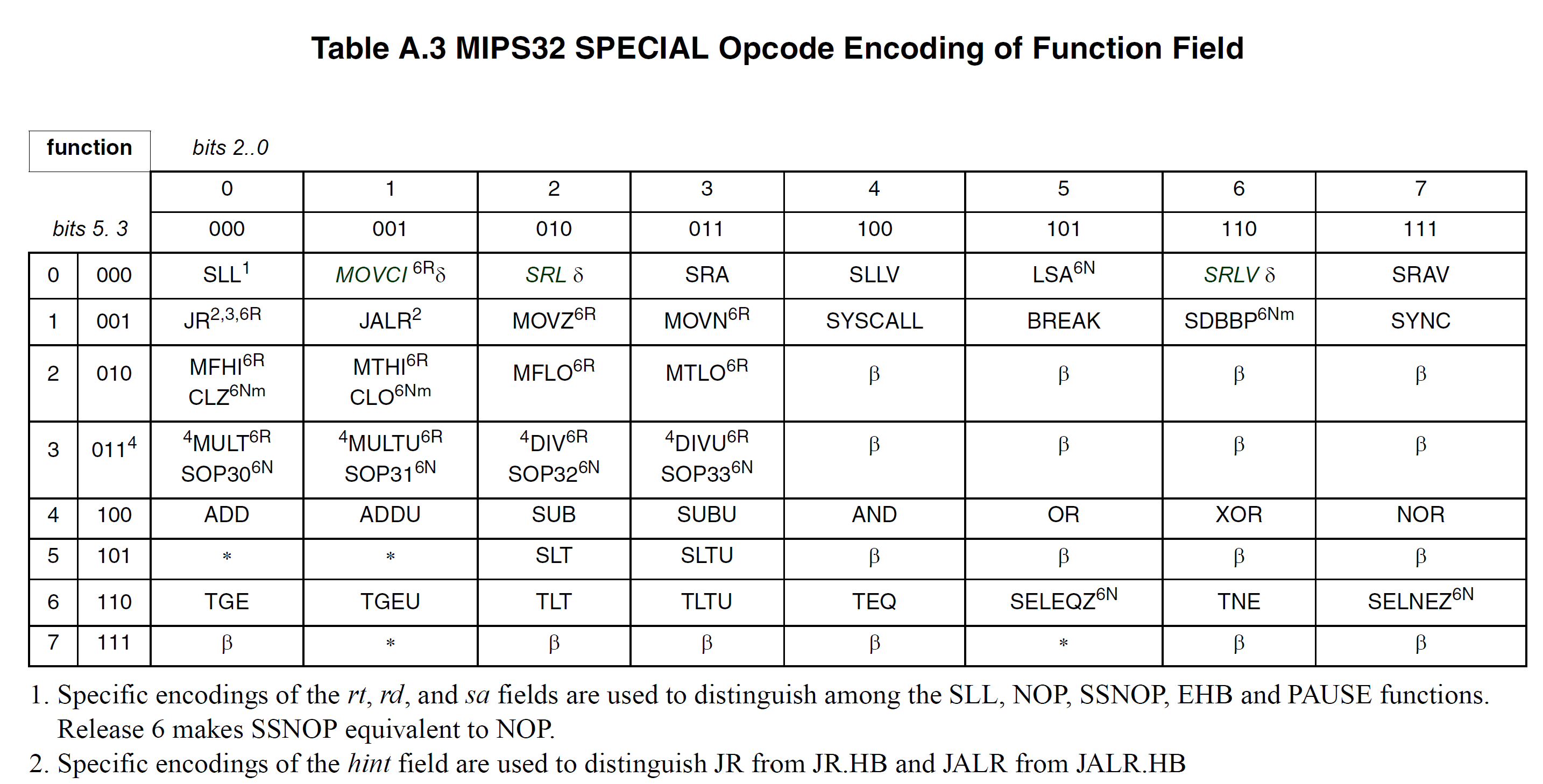
This shows that now we're looking at bits 5 through 0, which are the rightmost 6 bits. In our case, these are 000_000. The row is the upper three bits and the column is the lower three bits. So, again, we are row 0 and column 0. This brings us to the SLL instruction.
We now know what instruction to look for. We go back to chapter 3 and find the SLL instruction for the rest of the decoding. Just like with encoding, we need rt, rd, and sa (shift amount). We decode these just the opposite of how we encoded them to get $t0 for rd, $s3 for rt, and 3 for sa.
There isn't any magic to this, but there are so many places you can make a mistake. If you misplace one bit, the entire scheme will be thrown off. Always make sure to double check your work!
Branch Instructions
Branch instructions must be treated with a little bit more respect. Recall that we use two registers followed by a memory label. The CPU doesn't care what you called the label, it only cares about the memory address. So, when we decode a branch instruction, we will get a memory address.
Another interesting part of a branch instruction is that the memory address is an offset. If this value is negative, it is telling you to go backwards. If this value is positive, it is telling you to go forwards. Let's see an example:
main:
   add $a0, $a0, $zero
   sub $a0, $a0, $a0
   bne $t0, $a0, main
The instruction don't really do anything, but let's see how bne is encoded. First, we go to chapter 3 and find the BNE instruction which I show below.
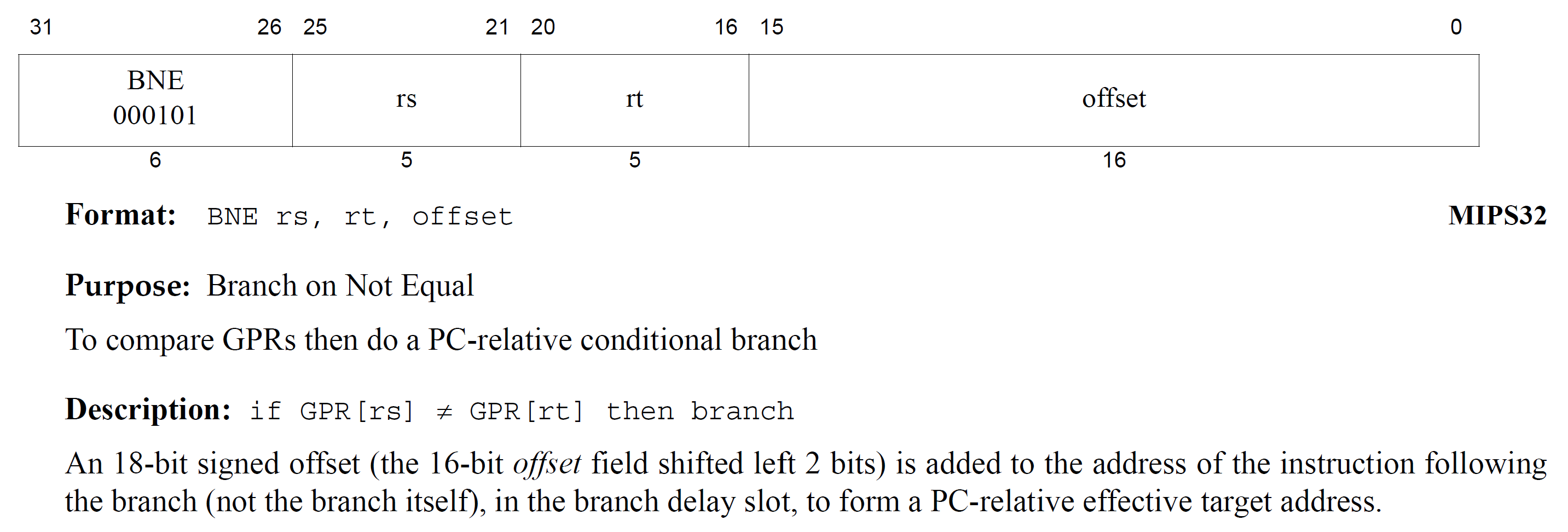
We can see that the two registers we compare with are rs and rt and that the offset is only 16 bits! If we look back at the assembly code, we see that the main label is BACKWARDS (above) the branch instruction. This means that the 16-bit offset will be negative--remember your two's complement!
Luckily, each instruction is exactly 4 bytes, so that makes our lives a little easier. We can also see by the description that the offset is actually 18 bits. What we store is only the upper 16 bits of the offset. This means we right shift the offset by 2 places, which essentially divides by 4.
Notice that the description says that the offset is added to the FOLLOWING instruction, and NOT the branch itself. This means that if we want to go back to the branch, we would have to go back 4 bytes (-4 offset). In our case, main labels the add instruction, so we need to move up by 4 to get to the branch, another 4 to get to the sub, and yet another 4 to get to the add instruction. So, all-in-all, we need to subtract 12 from the PC. However, remember that before we store our offset we must divide it by 4 (right shift two places). So, we need to subtract \(\frac{-12}{4}=-3\).
To get -3 using 16 bits, we first take 3 and then take the two's complement: \(\text{~}0000\_0000\_0000\_0011_2+1=1111\_1111\_1111\_1100+1 = 1111\_1111\_1111\_1101\). So, our offset is 0xfffd. So, let's encode $t0 and $a0, which are 8 and 4, respectively. So, now we have all of the information we need to encode our instruction:
BNE $t0, $a0, 0xffd
$t0 = 8 = 0b01000
$a0 = 4 = 0b00100
OPCODE = 000_101

000101   rs     rt      offset
000101   01000  00100   1111 1111 1111 1101
0001 0101 0000 0100 1111 1111 1111 1101
 1    5    0    4    f    f    f    d
So, this branch instruction encodes into 0x1504_fffd.
To encode a branch always remember the offset starts at the instruction AFTER the branch itself. Furthermore, each instruction is exactly 4 bytes. Finally, always divide your offset by 4 before storing it as a 16-bit value.
Notice that only BNE and BEQ are the only instructions encoded in MIPS. All of the other conditions are pseudo-instructions. They use a combination of SLT (set on less than) followed by a BNE or BEQ to get the same effect. As with all other instructions, make sure you're not encoding a pseudo-instruction!
Limitations for Jump and Branch
As you know, all instructions are encoded using 4 bytes. However, this means that the distance that we can jump is limited. If we have a 32-bit memory address, we can address about 4GB of memory. However, that would take the entire instruction. The jump instruction still has a 6-bit opcode, but then it has a 26-bit non-PC-relative target address. This means that unlike a branch instruction, this is NOT an offset added or subtracted from the current location. Instead, it is an absolute memory address. To form a 32-bit memory address, the jump instruction will take the 26-bit address, shift it left by 2 places to form a 28-bit memory address. The upper part of the memory address is zero-extended. This means that the range of a jump is \(2^{28}=256~\text{MB}\).
This doesn't mean we are limited to only 256 megabytes of memory. Instead, we can place branch instructions at the end of the memory to move us out of the 256 megabyte memory range. So, the jump instruction will jump to a branch instruction, which will then branch by adding the offset to the program counter to get to the actual instruction we want to run. The branch instruction in this case is called a veneer since its only purpose is to extend our operating range. Below is an example of a veneer.
.text
j goto_veneer
add $t0, $t0, $t0
add $t0, $t0, $t0
add $t0, $t0, $t0
add $t0, $t0, $t0
add $t0, $t0, $t0
add $t0, $t0, $t0
add $t0, $t0, $t0
add $t0, $t0, $t0
add $t0, $t0, $t0
add $t0, $t0, $t0
add $t0, $t0, $t0
# several more instructions
goto_veneer:
    beq $zero, $zero, go_func
# several more instructions
go_func:
    addi $sp, $sp, -8
    sw $ra, 0($sp)
    lw $ra, 0($sp)
    addi $sp, $sp, 8
    jr $ra
In the code above, the jump instruction needs to jump to a memory range. The veneer is actually within the 256MB range. Since a branch instruction can add to the current PC, we can keep adding veneers to get to where we want to go. Think of this as a relay-race. The jump hands off the control to the branch instruction, which finally gets us to the function we want to get to.
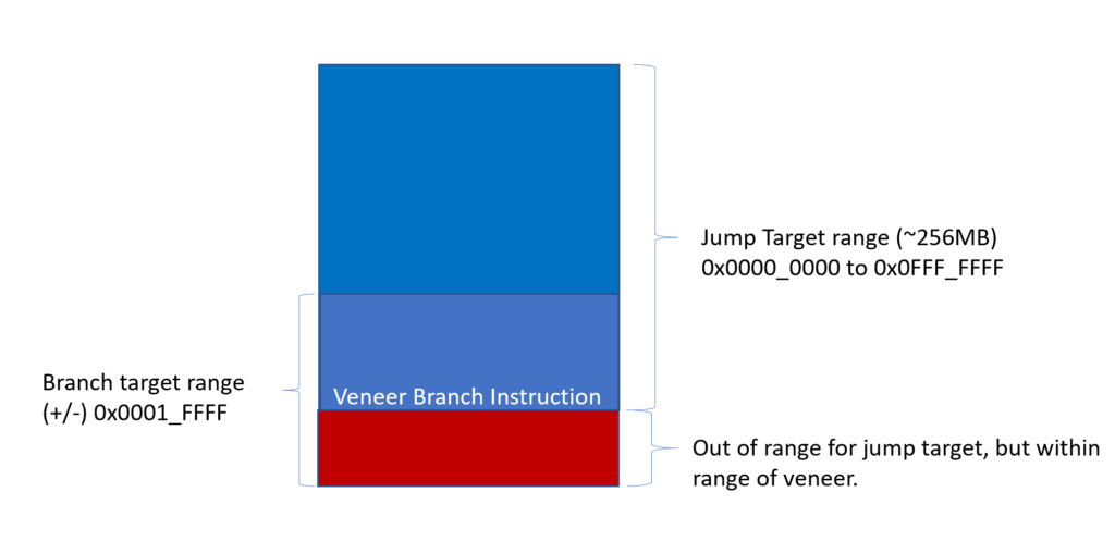
The figure above shows the range of each instruction. notice that the veneer is placed close to the edge of the jump target range and can extend it. Generally, an unconditional branch is used. The unconditional branch is usually something like beq $zero, $zero, label. Zero is equal to zero and the $zero register is always zero, so no matter what, this beq will always be true and jump to the label.
The jump and branch ranges are calculated by looking at how much address information we can store in the instruction itself. The jump has a 26-bit index encoded in the instruction. This is shifted left by two places to give us a 28-bit address. This address can be all zeroes or it could be all ones meaning our range is \([0, 2^{28})\) or 0x0000_0000 to 0x0FFF_FFFF. The branch instruction has a 16-bit, signed offset encoded in the instruction itself. This is also shifted left to give us an 18-bit, signed offset. Since the 18th bit is the sign bit, we only have 17 bits to encode the information. So, we have \([0, 2^{17})\) or -0x0001_FFFF through +0x0001_FFFF.