Learning Objectives
- Be able to identify certain sections of a central processing unit (CPU).
- Be able to identify functional units in the CPU.
- Understand what components make up an Arithmetic and Logic Unit (ALU).
- Understand what sets the NZCV flags of the ALU's status register.
- Understand that the FPU and ALU are in different CPU sections.
- Understand how dynamic RAM is built.
- Understand the difference between dynamic RAM and static RAM.
Central Processing Unit (CPU)
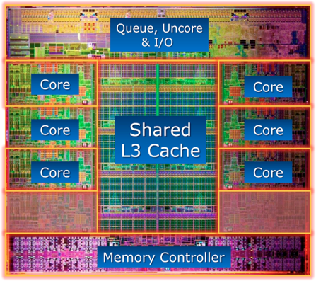
The central processing unit (CPU) is where all of the instructions are executed. Most central processing units nowadays contain multiple cores. These cores contain functional units. A single CPU can execute two, three, four, or even eight (depending on the number of cores) integer instructions simultaneously!
Arithmetic and Logic Unit (ALU)
The arithmetic and logic unit (ALU) performs integer arithmetic and logic instructions (go figure). It is purely combinational logic, and its job is to perform binary arithmetic. The ALU is also used to calculate offsets for load and store instructions. For example, ld $s0, 4($sp) will require the $sp register to be added with 4. The ALU will take 4 and $sp and add them together.
ALU Status Register
The ALU has two inputs for the operands, but it has two outputs: (1) the result and (2) the status. The result is important for integer and logic arithmetic, however what is the status used for? The status can also be called NZCV, which stands for Negative, Zero, Carry, and oVerflow. So, as you can see, the status is just what happened after the ALU performed its operation. This is important when we execute branch instructions.
So, how can we implement branching in the ALU? Well, first, we take the difference of both operands. If the Zero status flag is set, that means that the difference of the two operands was zero. This would mean that beq would be true, and it would take the branch. If the instruction was bne, it would NOT take the branch unless the \(\bar Z\) condition was met. So, you can see how we can use combinational logic to implement branching in our ALU.
The negative flag can be used to implement the SLT (set-on-less-than) instruction. We essentially copy the negative bit into the destination. So, if I subtract two numbers and the result is negative, that means that the first number is smaller than the second, and hence the first number is less-than the second.
The carry flag means that when we performed binary arithmetic, we had to throw away some bit. This means that after the register was written, we had a carry-out (Cout) on the final bit (bit index 31 for a 32-bit register).
The overflow flag means that we performed binary arithmetic, and we possibly destroyed the sign bit. In other words, the result of binary arithmetic overflowed into the sign bit. Therefore, if we see that the overflow bit is set to 1, we can almost be assured our result is incorrect.
The only reason we need the carry and overflow flags is because we don't have an infinite precision for numbers in our CPU.
Random Access Memory (RAM)
The memory we use for temporary storage is called random access memory (RAM). The term random access just means that we can go to a certain byte in memory without having to first seek through all of the bytes before it. To clarify, sequential access is like a VHS tape or cassette tape. If I want to get to a song in the middle of a cassette tape, I need to fast forward through all other songs before it. This is unlike digital music. If I want a song, I just click that song and it doesn't care about any songs before it. This is called random-access.
We generally see dynamic RAM for large banks of RAM because it is simpler to implement, and using dynamic RAM is much more cost efficient. Dynamic RAM can store 1 bit by just using a capacitor (called a trench capacitor) and a transistor. That's it. However, using a capacitor leads to some issues. The capacitors are very small (actually microscopic) and they lose their charge over a short period of time--usually in microseconds or milliseconds. Therefore, we are required to design logic that will write the value back into the capacitor. The same goes for reading a bit. When we read a bit from the capacitor, it discharges. So, reads destroy the data, and yet again, we need to design logic that puts a value back into the capacitor after we destroy it.

Aligned vs Unaligned Access

DRAM is stored in rows and columns as you can see above. When we read a byte, halfword, or word, we use a selector to select the row that this is in. If the data falls completely within a row, this is called an aligned memory access. If the data requires a read across two rows, this is called an unaligned memory access.
Advantages
- Requires few components
- Can get very large capacity
- Can be developed relatively inexpensively
Disadvantages
- Requires complex "refresh" logic
- Requires complicated timings to implement refresh logic
- Data is lost as capacitors dissipate naturally or in response to a read
Static RAM
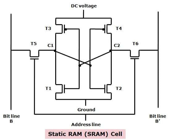
Static RAM is the opposite of dynamic RAM. Static RAM uses D-latches to store data, like we did during our digital logic phase. You can hopefully see why static RAM is much more expensive. Instead of 1 capacitor and 1 transistor, static RAM requires somewhere between 6 to 10 transistors per bit!

Static RAM uses the flip flops as we talked about previously in sequential circuits. A latch holds the bit, uses a feedback loop to contain the value.
Advantages
- Easy to implement.
- No strobing or "refreshing"
- Reads do not destroy the value
Disadvantages
- More expensive
- Requires more transistors and components
Connecting the Components
The components are connected using a bus, which just means a bundle of wires or one big wire.
